
Inductive Rotary Sensor Pcb
Inductive rotary sensor pcb refers to the printed circuit board used as an inductive rotary sensor. The inductive rotary sensor consists of two parts: an inductor and a printed circuit board. The inductor section includes a coil and a magnet, which achieve circuit output signals through...
Description
Inductive rotary sensor pcb refers to the printed circuit board used as an inductive rotary sensor.
The inductive rotary sensor consists of two parts: an inductor and a printed circuit board. The inductor section includes a coil and a magnet, which achieve circuit output signals through inductance. The board section includes key components such as analog-to-digital conversion circuit, signal filtering circuit, power amplification circuit, etc.
Inductive rotary sensor is a sensor used to measure rotation angle, which can accurately and high-precision record the direction and angle of rotation of rotating objects.
Inductive rotary sensor is a non-contact sensor with advantages such as high sensitivity, high resolution, and long service life. Therefore, it is widely used in fields such as mechanical fault diagnosis, position measurement, angle measurement, speed measurement, and dynamic control. The printed circuit board of the sensor is an important component to ensure the normal performance and accuracy of the sensor.
The inductive rotary sensor mainly consists of three parts: power supply, amplifier, and filter.
The power supply is the core part of the sensor, which provides power to the sensor and ensures its normal working state. The power supply section is usually composed of a regulated power supply and a filtering circuit, which provides stable voltage through the regulated power supply and removes interference such as power noise and leakage through the filtering circuit.
The amplifier part mainly amplifies and processes the sensor signal, amplifying the weak signal collected by the sensor to a range that can be read or processed by the control system. The amplifier part usually uses an operational amplifier circuit, which amplifies and filters the input signal of the sensor to ensure that the signal has sufficient amplitude and quality for processing by the next level of circuit.
The filter part is mainly used to remove noise during sensor data collection, so that only the original signal is recorded and analyzed during data collection, avoiding the impact of noise. The signals of inductive rotary sensors are usually high-frequency and low amplitude signals, which are prone to interference during signal acquisition. Therefore, it is necessary to filter through filters to remove interference and noise, and ensure the quality and accuracy of the signal.
Inductive rotary sensor pcb is an important component of sensor performance, with characteristics such as stability, high accuracy, and high sensitivity. With the continuous expansion of sensor application fields and increasing demand in recent years, the printed circuit board of inductive rotary sensors will become increasingly important.


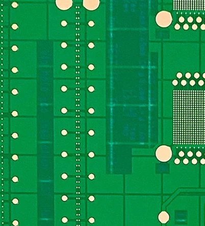
Picture:Inductive rotary sensor pcb
The specification of sample board
Item:Inductive rotary sensor pcb
Material:S1000-2M
Layer:4
Board thickness:1.3±0.13mm
Surface treatment:Immersion Tin
Hot Tags: inductive rotary sensor pcb, China inductive rotary sensor pcb manufacturers, suppliers, factory, health care pcb, Correspondence PCB, Single layer through hole pcb, temperature and humidity recorder board, double layer through hole pcb, Blue PCB Board
Send Inquiry
You Might Also Like