The introduciton of Radar antenna PCB
Leave a message
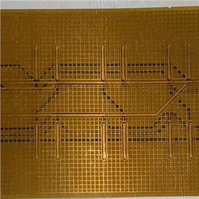
Radar antenna PCB is a special kind of board. Due to its RF, EMI and other characteristics, it needs to have good control in the manufacturing process. It is characterized by using a limited capacitor to provide frequency band, modulating the signal with a full-port microstrip linear oscillator, using an improved multi-step impedance matching circuit to transmit power, and using LNA elements to amplify the antenna response, making the input signal more stable and suppressing radio frequency interference. It is relatively difficult to make because it needs to consider broadband, range, multi-step impedance and very strict noise requirements.
The application products of radar antenna PCB cover a wide range. Common high-precision application scenarios include speed radar, detection radar, interceptor missile radar, search radar and shipborne fire control radar.
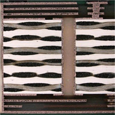
In the production process of radar antenna PCB, special attention should be paid to the main control points, mainly including the quality control of placement position and size, pin position, impedance, diameter-width ratio, line resistance, wiring structure, pad alignment, testing and packaging process. At the same time, it is also necessary to control the interference between the PCB coupling and other components to ensure its high efficiency.